Pneumatic Pressure Control Valves (Brisbane) – A Comprehensive Guide
Please note, if you are a professional pneumatics technician, please view our range of pneumatic valves or contact us directly for expert pneumatic componentry assistance:
Call 07 3344 4711 or Click Here to contact us online.
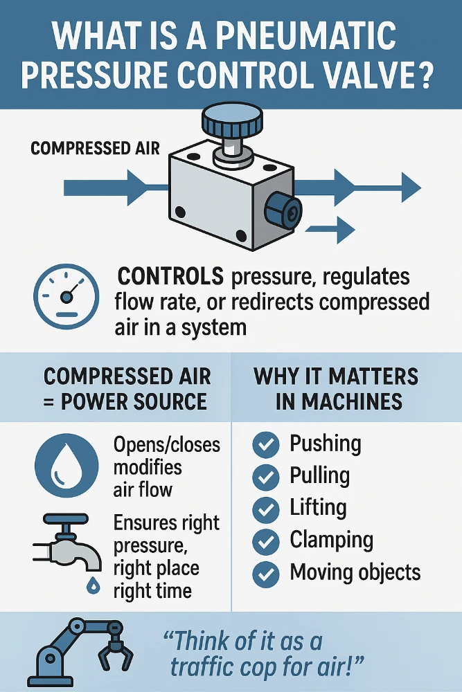
If you’ve ever wondered how machines use compressed air to get things done? It often involves gadgets called pneumatic pressure control valves. They might sound complicated, but they’re really just like traffic lights for air! They control how much air goes where, and when.
This guide is here to walk you through everything you need to know about them. We’ll keep things simple, practical, and friendly. Whether you work with machines, are studying engineering, or are just curious, you’re in the right place!
1. Introduction to Pneumatic Pressure Control Valves
Let’s start with the basics, shall we?
1.1 Definition and Basic Function
So, what is a pneumatic pressure control valve?
At its heart, it’s a device that manages the pressure, flow rate, or direction of compressed air in a system. Think of compressed air like water flowing through pipes, but instead of water, it’s air squeezed into a smaller space, giving it energy. These valves act like taps or switches for that air.
Their main job is to make sure the right amount of air pressure gets to the right part of a machine at the right time. This allows machines to push, pull, lift, clamp, or move things automatically. Pretty neat, right?
1.2 Historical Development and Evolution
Using air power isn’t exactly new! People have used bellows to fan fires for thousands of years. But using compressed air in complex machines started picking up steam (or should we say, air?) during the Industrial Revolution in the 1800s. Early uses included rock drills in mining and railway brakes.
The valves back then were simple, often operated by hand. Over time, especially in the 20th century, things got much smarter. New materials were developed, designs became more precise, and different ways to control the valves (like using electricity) came along. From clunky mechanical contraptions, they’ve become smaller, faster, and much more reliable components found in countless machines today.
1.3 Importance in Modern Industrial Systems
Why are these valves so important now? Well, compressed air is a fantastic way to power things in factories and workshops. It’s:
- Clean: Air leaks don’t make a mess like oil leaks can. This is great for industries like food processing or electronics.
- Safe: It can often be used safely in places where electric sparks might be dangerous, like around flammable materials.
- Relatively Cheap: Generating compressed air costs money, but the systems themselves can be simpler and less expensive than some other options.
- Fast: Air can make things move very quickly!
- Reliable: Pneumatic systems are known for being tough and lasting a long time with proper care.
Because of these benefits, pneumatic control valves are everywhere! They are essential parts in automation, helping factories run smoothly and efficiently. Without them, many of the products we use every day simply couldn’t be made as quickly or cheaply.
1.4 Key Components and Terminology
Let’s learn a few key words you’ll hear when talking about these valves:
- Body: The main casing of the valve, holding everything together. Usually made of metal or strong plastic.
- Port: The openings on the valve body where air pipes connect (inlet, outlet, exhaust).
- Actuator: The part that makes the valve switch positions. This could be a handle (manual), a coil of wire using electricity (solenoid), an air signal (pilot), or a spring/lever (mechanical).
- Spool or Poppet: The moving part inside the valve that blocks or opens the pathways for air to flow. Think of it like the moving gate in our traffic light idea.
- Seals: Rings or discs (often rubber or plastic) that stop air from leaking where it shouldn’t.
- Spring: Often used to return the spool or poppet to a ‘normal’ position when the actuator isn’t active.
Don’t worry if these terms seem a bit much right now; we’ll see them in action as we go!
1.5 Pneumatic vs. Hydraulic vs. Electric Control Systems
How does air power (pneumatic) compare to oil power (hydraulic) or direct electricity (electric)?
- Pneumatic (Air): Uses compressed air. Good for fast movements, clean environments, and relatively simple tasks. Not so good for very heavy loads or extremely precise speed control compared to hydraulics.
- Hydraulic (Oil): Uses pressurised liquid (usually oil). Excellent for moving very heavy loads and precise control. Can be messy if leaks occur and often needs more robust (and sometimes more expensive) equipment.
- Electric (Electricity): Uses electric motors and actuators (like solenoids or linear actuators). Very precise control, easy to connect to computers, and getting cheaper. Can be complex, and might not be suitable for all environments (e.g., explosive atmospheres, unless specially designed).
Often, systems use a mix! For example, an electric signal might tell a pneumatic valve to open. Each type has its strengths, and engineers choose the best tool for the job.
2. Fundamental Principles of Pneumatic Pressure Control
Alright, let’s get into how these valves actually work with air.
2.1 Basic Pneumatic Theory
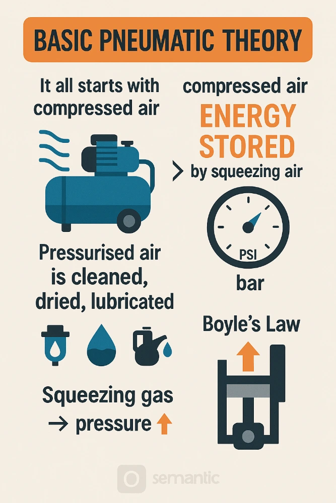
It all starts with compressed air. Air from the atmosphere is squeezed by a machine called an air compressor. Squeezing the air forces the molecules closer together, storing energy – this is pressure. We usually measure this pressure in units like PSI (pounds per square inch) or bar (another metric unit, common in Australia and Europe. 1 bar is roughly 14.5 PSI).
This pressurised air is then cleaned, dried (water vapour removed), and sometimes lubricated before being sent through pipes to power machines. The valves are the key components that direct and control this stored energy. Remember Boyle’s Law from school science? It basically says if you squeeze a gas into a smaller space, its pressure goes up (assuming temperature stays the same). That’s the core idea!
2.2 Pressure Regulation Concepts
One of the most common jobs for a pneumatic valve is pressure regulation, also known as pressure reduction. Imagine the air from your compressor is at 10 bar (about 145 PSI), but the tool you want to use only needs 6 bar (about 87 PSI). Using too much pressure could damage the tool or make it work incorrectly.
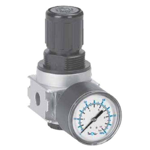
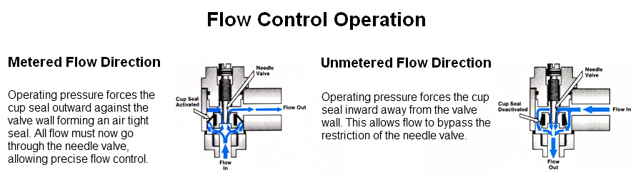
A pressure regulator (a type of pressure control valve) steps in. It takes the high-pressure air coming in (inlet pressure) and reduces it to a lower, steady pressure going out (outlet pressure), regardless of small changes in the inlet pressure or how much air the tool is using. It works by balancing forces inside – usually a spring pushing down and the outlet air pressure pushing up on a diaphragm or piston. Clever, eh?
2.3 Flow Characteristics and Coefficient Values
How much air can flow through a valve? This is super important for making sure tools or cylinders get enough air to work properly and quickly.
We measure this using a value called the Flow Coefficient, often written as Cv (or sometimes Kv in metric systems). A higher Cv value means the valve can let more air through, like a wider pipe lets more water through. Manufacturers test their valves and provide these Cv values. When choosing a valve, you need to make sure its Cv is large enough for the air flow your machine needs. Too small, and things might move slowly or not have enough force.
2.4 Response Time and Dynamic Performance
How quickly does the valve react when you tell it to open or close? This is its response time. For some jobs, like quickly sorting items on a conveyor belt, a super-fast response time (measured in milliseconds – thousandths of a second!) is needed.
Dynamic performance describes how the valve behaves as it’s opening, closing, or adjusting pressure. Does it react smoothly? Does it overshoot the target pressure before settling? These factors matter in systems needing precise and stable control.
2.5 Operating Parameters and Specifications
When looking at a valve’s datasheet, you’ll see important numbers called operating parameters or specifications. These tell you what the valve is designed for:
- Pressure Range: The minimum and maximum air pressure the valve can handle safely.
- Temperature Range: The lowest and highest temperatures the valve can work in. Air gets hot when compressed, and environments can be cold or hot.
- Port Size: The size of the connections for the air pipes (e.g., 1/4 inch, 1/2 inch, etc.).
- Flow Rate (Cv/Kv): As we just discussed, how much air it can pass.
- Voltage (for Solenoid Valves): If it’s electrically controlled, what voltage it needs (e.g., 24V DC, 240V AC).
Materials: What the body and seals are made from.

Matching these specs to your system’s needs is key to choosing the right valve.
3. Comprehensive Classification of Pneumatic Pressure Control Valves
Okay, valves aren’t all the same! They come in different types, each designed for a specific job. Let’s break them down.
3.1 Pressure Relief Valves
Think of these as safety valves. Their job is to protect the system from too much pressure. If the pressure builds up higher than it should (maybe the compressor control failed, or something got blocked), the relief valve opens automatically and vents the extra air, usually to the atmosphere. This stops pipes from bursting or equipment from getting damaged. Safety first!
- 3.1.1 Direct-Acting Relief Valves: These are simple. The system pressure pushes directly against a spring-loaded poppet or ball. When the pressure force gets stronger than the spring force, the valve cracks open. Simple and reliable for many jobs.
- 3.1.2 Pilot-Operated Relief Valves: These are a bit more complex but often handle larger flows or offer more precise control. They use a small ‘pilot’ valve to control a much larger main valve. System pressure helps to keep the main valve tightly shut until the pilot valve senses the overpressure limit and triggers the main valve to open fully and quickly.
- 3.1.3 Cracking Pressure and Override Considerations:
- Cracking Pressure: The exact pressure at which the valve starts to open.
- Full Flow Pressure: The pressure at which the valve is fully open and venting the maximum amount of air it can handle.
- Override: The difference between the cracking pressure and the full flow pressure. You want this difference (override) to be reasonably small, so the pressure doesn’t climb too high before the valve fully opens.
- Reseat Pressure: The pressure at which the valve closes again after the overpressure situation is fixed. This is always lower than the cracking pressure.
3.2 Pressure-Reducing Valves (Regulators)
We touched on these earlier. Their job is to take a higher, possibly fluctuating, inlet pressure and provide a steady, lower outlet pressure. You set the desired outlet pressure (often with a knob or screw), and the valve works automatically to maintain it. Essential for supplying the right pressure to tools and actuators.
- 3.2.1 Direct-Acting Reducers: Similar to direct-acting relief valves, the outlet pressure acts directly (usually via a diaphragm) against an adjustable spring. If the outlet pressure drops, the spring pushes the valve open more to let more air in. If it rises, the pressure pushes the valve closed a bit. Simple, common for general use.
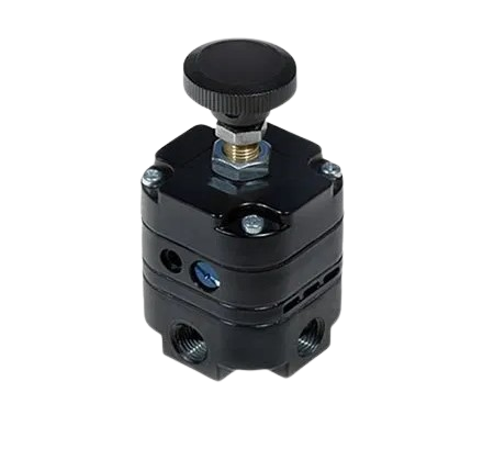
- 3.2.2 Pilot-Operated Reducers: Again, these use a pilot stage for more precise control, better stability (less fluctuation in outlet pressure), and often higher flow rates. Good for sensitive applications or where demand for air changes a lot.
- 3.2.3 Constant vs. Variable Pressure Reduction: Most common reducers provide a constant (set) outlet pressure. Some specialised valves might allow the outlet pressure to be varied automatically based on another signal, but standard regulators aim for a steady output.
3.3 Sequence Valves
What if you want one action to happen after another? For example, you want a clamp to grip a workpiece first, then a drill to move down. A sequence valve makes this happen!
- 3.3.1 Operating Principles: A sequence valve is normally closed. It senses the pressure in one part of the circuit (e.g., the pipe going to the clamp cylinder). Only when the pressure in that first part reaches a certain level (meaning the clamp is fully engaged), does the sequence valve open and allow air to flow to the next part of the circuit (the drill cylinder).
- 3.3.2 Applications in Multi-Actuator Systems: Perfect for ensuring operations happen in the correct order in machines with multiple moving parts (actuators like cylinders or motors). They prevent chaos and make sure processes run safely and correctly.
3.4 Counterbalance Valves
Imagine lifting a heavy load with a pneumatic cylinder, or controlling a load that wants to run away downhill. If the air supply fails, the load could drop suddenly! A counterbalance valve prevents this.
- 3.4.1 Load Control Applications: It’s installed in the line supporting the load. It acts like a pressure-controlled brake. It only allows air to leave the cylinder (letting the load lower) if there is enough pilot pressure (usually from the line trying to lower the load) to overcome its spring setting plus the pressure created by the load itself. This provides smooth, controlled lowering and holds the load securely if pressure is lost. Essential for safety with vertical or overhanging loads.
- 3.4.2 Anti-Cavitation Features: Sometimes, if a load tries to run away faster than the air supply can keep up, it can create a vacuum (cavitation) in the cylinder, leading to jerky movement. Some counterbalance valves have built-in check valves to allow air to be drawn back into the cylinder from the tank line to prevent this.
3.5 Unloading Valves
Air compressors use energy. If the system isn’t actually doing much work for a while, but the compressor keeps running to maintain pressure against a relief valve, that’s wasted energy. An unloading valve helps save energy.
- 3.5.1 Energy Efficiency Applications: When the system reaches its required pressure (often stored in a receiver tank), the unloading valve opens. It directs the compressor’s output flow back to the tank or atmosphere at very low pressure, allowing the compressor motor to run under minimal load (or even switch off), saving electricity. When system pressure drops again, the unloading valve closes, and the compressor pumps air back into the system.
- 3.5.2 System Integration Considerations: They need to be integrated correctly with the compressor, receiver tank, and possibly pressure switches to work effectively and make genuine energy savings.
3.6 Directional Control Valves (DCVs)
These are probably the most common type you’ll picture. They don’t usually control the level of pressure, but rather where the air goes. They start, stop, and change the direction of airflow to make actuators (like cylinders) move back and forth.
They are described using two numbers: Ways and Positions.
- Ways: How many pipe connection points (ports) the valve has.
- Positions: How many distinct flow paths the valve can switch between.
Let’s look at common types:
- 3.6.1 Two-Way, Two-Position Valves (2/2): Simplest type. Two ports (inlet, outlet). Two positions (open or closed). Like a simple on/off switch for air.
- 3.6.2 Three-Way, Two-Position Valves (3/2): Three ports (inlet, outlet, exhaust). Two positions. Often used to control single-acting cylinders (which push out with air, but return with a spring). In one position, air goes from inlet to outlet (pushing cylinder out). In the other position, the inlet is blocked, and air from the outlet goes to the exhaust (letting cylinder return).
- 3.6.3 Four-Way, Two-Position Valves (4/2): Four ports (inlet, two outlets A & B, exhaust). Two positions. Used for double-acting cylinders (which use air to move both out and back). In position 1, inlet goes to A, and B goes to exhaust (cylinder moves one way). In position 2, inlet goes to B, and A goes to exhaust (cylinder moves the other way).
- 3.6.4 Four-Way, Three-Position Valves (4/3): Four ports, but three positions. The two end positions are like the 4/2 valve. The centre position is special. Common centre positions are:
- Closed Centre: All ports blocked. Cylinder stops and holds position (if leak-tight).
- Exhaust Centre: Both cylinder ports (A & B) connected to exhaust. Cylinder can be moved freely by hand.
- Pressure Centre: Both cylinder ports connected to inlet pressure. Cylinder is held firmly in position by pressure on both sides.
Understanding these numbers helps you pick the right DCV for controlling your cylinders or air motors.
4. Actuation Methods and Control Systems
How do we actually make these valves switch from one state to another? That’s actuation!
4.1 Manual Actuation
The simplest way! You physically operate the valve using:
- Levers: A handle you move.
- Push Buttons: Press to activate.
- Foot Pedals: Use your foot, keeping hands free.
- Twist Knobs: Turn to select a position.
Great for direct human control, setups, or emergency stops.
4.2 Solenoid Actuation
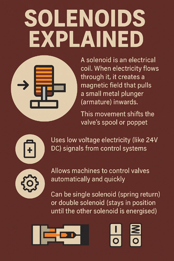
Very common in automated systems. A solenoid is an electrical coil. When electricity flows through it, it creates a magnetic field that pulls a small metal plunger (armature) inwards. This movement shifts the valve’s spool or poppet.
- Uses low voltage electricity (like 24V DC) signals from control systems.
- Allows machines to control valves automatically and quickly.
- Can be single solenoid (spring return) or double solenoid (stays in position until the other solenoid is energised).
4.3 Pilot Actuation
Uses air pressure itself to switch the valve! A separate, low-pressure air signal (the pilot signal) is sent to the valve’s actuator port. This air pressure pushes on a piston or diaphragm inside the actuator, shifting the main valve spool.
- Good for situations where electrical signals might be unsafe or unavailable.
- Can use air signals generated by other pneumatic components (like limit switches or other valves).
- Can be single pilot (spring return) or double pilot (stays shifted until an opposite pilot signal is received).
4.4 Mechanical Actuation
The valve is switched by direct physical contact with a moving part of the machine.
- Roller Lever: A wheel on a lever is pushed down by a cam or moving part.
- Plunger: A small pin is pushed directly.
Often used as limit switches – detecting when a cylinder has reached the end of its travel, for example.
4.5 Electronic Proportional Control
This is more advanced. Instead of just being fully open or fully closed, a proportional valve can open partially. The amount it opens is proportional to an electrical input signal (like a varying voltage or current).
- Allows very fine control over pressure or flow rate.
- Used in applications needing precise speed control, force control, or pressure profiling.
- Often includes electronics built into the valve itself.
4.6 Integration with PLC and Control Networks
In modern factories, valves rarely work alone. They are usually part of a larger automated system controlled by a PLC (Programmable Logic Controller) – basically, the machine’s brain.
- Solenoid valves and proportional valves connect directly to PLC output modules.
- Sensors (like pressure switches or cylinder position sensors) feed information back to the PLC input modules.
- Increasingly, valves are connected using control networks or fieldbus systems (like IO-Link, AS-Interface, Profibus, EtherNet/IP). This uses special wiring that allows many valves and sensors to communicate with the PLC over a single cable, reducing wiring complexity and providing more diagnostic information.
5. Material Considerations and Construction
What are these valves made of, and why does it matter?
5.1 Body Materials and Corrosion Resistance
The valve body needs to be strong enough to handle the pressure and tough enough for the working environment. Common materials include:
- Brass: Good corrosion resistance, easy to machine. Common for smaller valves.
- Aluminium: Lightweight, good heat dissipation. Often used for valve bodies, especially for manifold mounting. Can be anodised for better surface hardness and corrosion resistance.
- Stainless Steel: Excellent corrosion resistance, strong, good for high temperatures. Used in food processing, chemical plants, offshore, or harsh environments. More expensive.
- Zinc Die-Cast: Cost-effective for some designs.
- Plastic/Polymer: Lightweight, corrosion-proof, good for medical or food applications, but may have lower pressure/temperature limits.
Choosing the right material prevents rust (corrosion) and ensures the valve lasts a long time.
5.2 Seal and Seat Materials
Seals are vital to stop air leaking! They need to be compatible with the air (or gas) being used, the temperature, and any lubrication present. Common seal materials:
- Nitrile Rubber (NBR): Most common general-purpose seal. Good for standard air and oils, decent temperature range. Cost-effective.
- Viton® (FKM): Excellent for higher temperatures and better chemical resistance (e.g., against certain solvents or more aggressive lubricants). More expensive than NBR.
- EPDM: Good for water or steam applications, but not usually for mineral oils.
- Polyurethane (PU): Very tough and abrasion-resistant. Often used for piston seals in cylinders, sometimes in valves.
- PTFE (Teflon®): Very wide temperature range and excellent chemical resistance. Often used for valve seats (where the moving part seals against the body) or in special seal designs.
The seat is the surface inside the valve that the moving element (poppet or spool) seals against. It might be part of the metal body or a separate insert made of a polymer like PTFE or PEEK for better sealing and longer life.
5.3 Environmental Considerations
Where will the valve be used?
- Indoors vs. Outdoors: Outdoor use needs better weather protection (water, UV rays).
- Washdown Areas: Food or pharmaceutical plants often require valves that can withstand regular cleaning with water or chemicals (stainless steel bodies, high IP-rated enclosures for solenoids).
- Dusty/Dirty Environments: Seals need to be protected from grit. Proper filtration of the air supply is key.
- Explosive Atmospheres (ATEX/IECEx zones): Special certified valves are required that won’t cause a spark.
5.4 Temperature and Pressure Limitations
We mentioned these before, but they are critical material considerations.
- High Temperatures: Can degrade seals, affect solenoid performance, and reduce material strength. Need high-temp seals (like FKM) and appropriate body materials.
- Low Temperatures: Can make seals brittle and cause leakage. Some materials become fragile. Special low-temp seals and materials might be needed.
- High Pressures: Require stronger bodies and designs that can withstand the forces involved.
Always check the manufacturer’s specifications!
5.5 Special Designs for Harsh Environments
For really tough conditions (like mining, offshore oil rigs, chemical processing), standard valves might not cut it. Special designs might include:
- All Stainless Steel Construction: For maximum corrosion resistance.
- Hermetically Sealed Solenoids: To prevent ingress of moisture or hazardous gases.
- Robust Actuators: To withstand vibration or impact.
- Special Coatings: For extra protection against chemicals or abrasion.
6. Applications Across Industries
Where do we actually use these pneumatic pressure control valves? Pretty much everywhere machines are used!
6.1 Manufacturing and Assembly
This is a huge area for pneumatics.
- 6.1.1 Automotive Applications: Car factories use countless pneumatic valves for robots welding car bodies, clamping parts during assembly, operating paint spray guns, moving components along production lines, and powering air tools used by workers.
- 6.1.2 Electronics Manufacturing: Precise, clean movements are needed. Pneumatic grippers handle delicate components like circuit boards and chips. Valves control pick-and-place machines and automated testing equipment.
- 6.1.3 Food and Beverage Processing: Cleanliness is key! Stainless steel valves control the flow of ingredients, operate filling and packaging machines, sort products, and clean equipment (washdown). Air is often preferred over hydraulics to avoid oil contamination.
6.2 Oil and Gas Industry
Used both onshore and offshore for controlling large process valves (using pneumatic actuators), operating safety shutdown systems, and in various control panels. Often requires robust materials and safety certifications (like ATEX for explosive areas).
6.3 Chemical Processing
Similar to oil and gas, used for controlling process flows, often requiring excellent chemical resistance (stainless steel or special alloys/plastics) and safety certifications. Pneumatic actuation is often chosen over electric in hazardous zones.
6.4 Pharmaceutical Applications
Requires extreme cleanliness and precision. Stainless steel valves meeting specific hygiene standards are used in manufacturing medicines, controlling bioreactors, operating tablet presses, and packaging equipment. Materials must be FDA-approved.
6.5 Power Generation
Used in power plants for various control functions, such as operating dampers in air systems, controlling turbine auxiliary systems, and in ash handling equipment. Reliability is very important here.
6.6 Mining and Heavy Industry
Tough environments demand tough equipment! Pneumatic valves operate drilling equipment, control ventilation doors, actuate large gates or chutes, and power heavy-duty tools. Robustness and reliability are paramount.
6.7 Transportation Systems
Think about trains and buses! Pneumatic valves control braking systems, door opening/closing mechanisms, suspension adjustments, and windscreen wipers. Reliability and safety are critical.
6.8 Aerospace and Defense
Used in ground support equipment, testing rigs (like simulating flight conditions), and sometimes even on aircraft for specific functions (like deploying landing gear or controlling certain surfaces, although hydraulics and electrics are more common for flight controls). Precision and reliability under extreme conditions are vital.
As you can see, they’re incredibly versatile!
7. Selection Criteria and Sizing Methodology
Choosing the right valve is important for performance, reliability, and cost. How do you do it? The easiest way is to give us a call here at Mastermac2000, as one of the longest-established and most experienced pneumatic parts suppliers to Brisbane and the Gold Coast.
Call 07 3344 4711 or contact us online https://mastermac2000.com.au/contact-us/
But here are some details about making the right pressure control valve choice.
7.1 System Requirements Analysis
First, understand the job the valve needs to do:
- What function is needed? (Pressure relief, reduction, direction control, sequencing?)
- What is being controlled? (A cylinder, air motor, process flow?)
- What are the operating conditions? (Pressure, temperature, flow rate needed?)
- What is the working environment like? (Clean, dirty, hazardous?)
- How will it be controlled? (Manual, solenoid, pilot?)
7.2 Performance Specifications
Based on the requirements, define the needed performance:
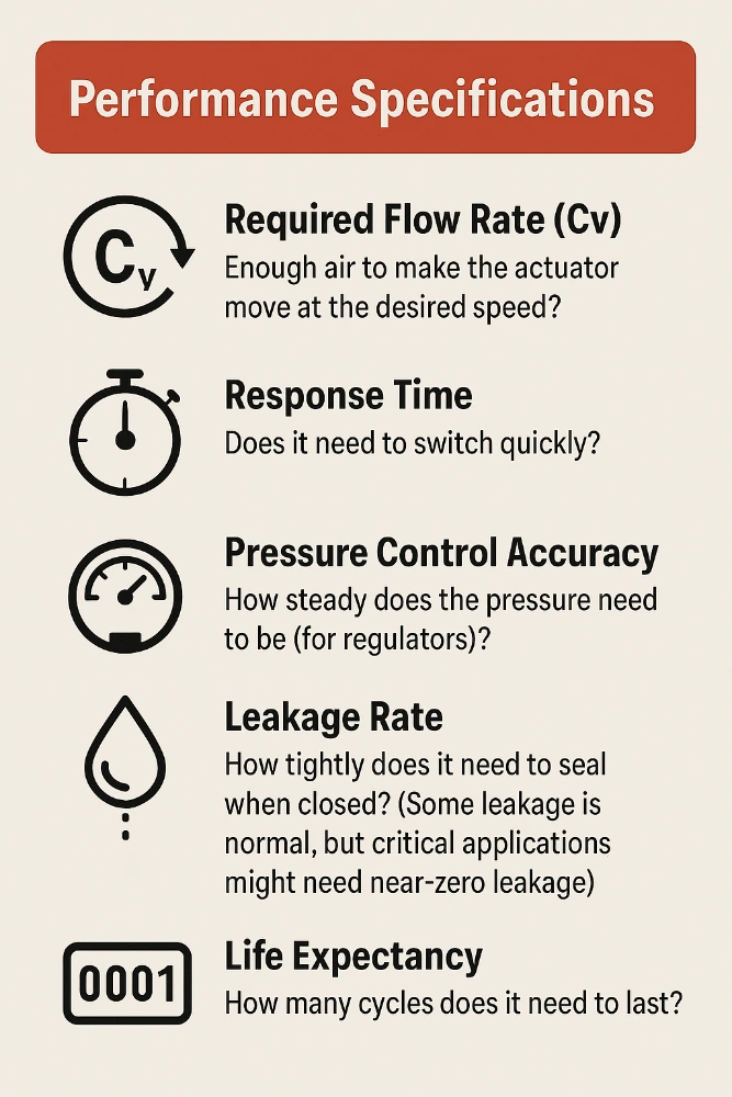
- Required Flow Rate (Cv): Enough air to make the actuator move at the desired speed?
- Response Time: Does it need to switch quickly?
- Pressure Control Accuracy: How steady does the pressure need to be (for regulators)?
- Leakage Rate: How tightly does it need to seal when closed? (Some leakage is normal, but critical applications might need near-zero leakage).
- Life Expectancy: How many cycles does it need to last?
7.3 Sizing Calculations and Formulas
Sizing usually focuses on getting the Flow Coefficient (Cv) right. You need to calculate the air flow required by the component (like a cylinder) based on its size, speed, and operating pressure. Then, you choose a valve with a Cv value that meets or slightly exceeds this requirement.
There are formulas and online calculators provided by manufacturers to help with this. A simplified idea for cylinders:
Flow needed depends on (Piston Area) x (Piston Speed) x (Pressure)
You’ll also need to consider pipe sizes – no point having a high-flow valve if the pipes feeding it are too small!
7.4 Environmental Considerations
We covered this under Materials, but it’s a key selection step:
- Temperature range?
- Exposure to moisture, chemicals, dust?
- Hazardous area classification (ATEX/IECEx)?
Choose materials and protection ratings (like IP ratings for electrical parts) accordingly.
7.5 Fail-Safe Requirements
What should happen if the power (electrical or air) fails?
- Should the valve go to a specific position (e.g., close, open, lock in place)? This determines if you need a spring-return valve (goes to a default state) or a detented/memory valve (stays put).
- For critical safety functions, specific fail-safe designs might be mandatory.
7.6 Cost vs. Performance Analysis
Valves range from cheap and simple to expensive and complex.
- Don’t over-specify! A high-performance valve might be unnecessary and costly if a standard one will do the job.
- Don’t under-specify! Choosing the cheapest option might lead to poor performance, breakdowns, and higher long-term costs.
Find the right balance for your specific application.
Following these steps helps narrow down the choices logically.
8. Installation Best Practices
You’ve chosen your valve! Now, let’s install it correctly.
8.1 Pre-Installation Planning
- Check the Valve: Make sure it’s the correct model you ordered and hasn’t been damaged in transit.
- Read the Manual: Manufacturer instructions are important!
- Gather Tools & Fittings: Have the right spanners, pipe sealant, and connectors ready.
- Safety First: Depressurise the air system before breaking into any lines! Lock out energy sources if needed.
8.2 Mounting Considerations
- Orientation: Some valves must be mounted in a specific way (e.g., regulators often need to be upright). Check the manual.
- Accessibility: Can you easily get to it for adjustments or maintenance later?
- Vibration: Avoid mounting valves directly onto heavily vibrating machinery if possible, or use vibration damping mounts.
- Manifold Mounting: Many directional valves can be mounted side-by-side on a manifold block. This saves space, reduces piping, and centralises connections.
8.3 Piping Requirements and Recommendations
- Clean Pipes: Make sure pipes are clean inside before connecting. Dirt can damage valve seals. Blow lines through with air first.
- Correct Size: Use pipes large enough to handle the required airflow without causing excessive pressure drop.
- Support Pipes: Don’t let the valve support the weight of long pipe runs. Use pipe clamps.
- Sealant: Use appropriate pipe sealant (like PTFE tape or liquid sealant) on tapered threads. Apply it correctly (leave the first couple of threads bare) to avoid sealant getting inside the valve.
- Avoid Strain: Don’t force pipes to line up with valve ports. This can distort the valve body and cause leaks or malfunction.
8.4 Filtration and Air Preparation
This is SO important! Dirty, wet, or oily air is the #1 enemy of pneumatic components. 💀 Always use a good Air Preparation Unit (or FRL – Filter, Regulator, Lubricator) upstream of your valves and actuators.
- Filter: Removes solid particles (dirt, rust) and bulk liquids (water, oil). Choose the right filtration level (e.g., 5 micron, 40 micron). Drain filters regularly (manual or auto-drain).
- Regulator: Sets the correct operating pressure (as we discussed).
- Lubricator (Optional): Adds a fine mist of special oil to the air to lubricate downstream components like cylinders and motors. Important: Not all modern components need lubrication (many are ‘lube-for-life’), and adding oil unnecessarily can sometimes cause problems (like gumming up valves or contaminating the environment). Only use a lubricator if the components specifically require it, and use the correct type/amount of oil.
8.5 Initial Setup and Calibration
- Connect Ports Correctly: Inlet to inlet, outlet to outlet, exhaust to exhaust (or silencer). Many valves have ports clearly marked (e.g., P=Pressure, A/B=Outlets, R/S or E=Exhaust).
- Electrical Connections (Solenoids): Wire correctly according to voltage and diagram. Ensure proper grounding. Use correct connectors (e.g., DIN connectors).
- Pressure Adjustment (Regulators/Reliefs): Slowly apply pressure and adjust the setting screw/knob to the desired pressure while monitoring a gauge.
- Test Function: Operate the valve manually or electrically and check that it switches correctly and the connected actuator moves as expected. Check for leaks using soapy water.
8.6 Common Installation Mistakes to Avoid
- Forgetting Filtration: Leads to premature valve failure.
- Using Incorrect Sealant/Applying Too Much: Sealant gets inside, causing jams or leaks.
- Overtightening Fittings: Can crack valve ports or distort the body.
- Reversing Connections: Valve won’t work, or system behaves unexpectedly.
- Ignoring Mounting Orientation: Can affect valve performance (especially regulators).
- Not Depressurising System First: Dangerous!
Take your time and do it right the first time!
9. Maintenance and Troubleshooting
Keep your valves happy and working well!
9.1 Preventative Maintenance Schedule
Regular checks can prevent breakdowns:
- Listen for Leaks: Hissing air means wasted energy and money. Find and fix leaks promptly.
- Check Filter Drains: Empty manual drains regularly. Check auto-drains are working.
- Inspect Air Quality: Is the air downstream of the filter clean and dry?
- Monitor Pressure Gauges: Are regulators holding steady pressure?
- Check Valve Operation: Do valves switch crisply? Is response time still good?
- Inspect Electrical Connections: Are they secure and free from corrosion?
- Check Lubricator Level (if used): Refill with the correct oil. Adjust drip rate if needed.
- Keep Valves Clean: Wipe down external surfaces.
The frequency depends on usage and environment (e.g., weekly checks in harsh conditions, monthly or quarterly in cleaner areas).
9.2 Performance Monitoring
Beyond basic checks, you might monitor:
- Cycle Times: Are machines running slower than they used to? Could be valve wear or flow issues.
- Pressure Drops: Is the pressure at the actuator significantly lower than at the regulator? Could indicate undersized valves/pipes or blockages.
- Leakage Rates: Use ultrasonic leak detectors for a more thorough check.
9.3 Common Failure Modes and Diagnostics
What can go wrong?
- Valve Fails to Shift:
- Cause: No actuation signal (electrical/pilot), stuck spool (dirt, wear, lack of lube), low pilot pressure, burnt-out solenoid coil, internal spring broken.
- Diagnose: Check signal, listen for solenoid click, check pilot pressure, try manual override (if fitted).
- Valve Leaks Externally:
- Cause: Damaged body seals, cracked body, loose fittings.
- Diagnose: Use soapy water to pinpoint leak.
- Valve Leaks Internally (Air passes to exhaust when it shouldn’t):
- Cause: Worn or damaged internal seals (spool seals, poppet seals), scored spool/bore.
- Diagnose: Listen for constant hissing at exhaust port when valve should be sealed. Check if actuator drifts.
- Regulator Pressure Unstable:
- Cause: Worn diaphragm/seat, dirt contamination, incorrect spring range.
- Diagnose: Check for steady output pressure under varying flow. Listen for chattering.
- Slow Response:
- Cause: Low pilot pressure, sticky spool, partial solenoid failure, flow restriction (e.g., dirty silencer).
- Diagnose: Check pressures, try manual override, clean/replace silencer.
9.4 Troubleshooting Guide (Symptom-Cause-Remedy Table)
| Symptom | Possible Cause | Possible Remedy |
| Valve won’t shift | No power to solenoid / No pilot signal | Check wiring, PLC output / Check pilot line, source |
| Solenoid coil burnt out | Replace coil | |
| Spool stuck (dirt, lack of lube, wear) | Clean valve internally, check lubrication, replace valve | |
| Low pilot pressure / Low supply pressure | Increase pressure (within limits), check for leaks | |
| Manual override engaged | Disengage override | |
| Actuator moves slowly | Undersized valve (Cv too low) | Select valve with higher Cv |
| Low supply pressure / Regulator set too low | Check/adjust pressure | |
| Flow restriction (kinked hose, blocked fitting) | Check piping, clear obstruction | |
| Exhaust blocked (dirty silencer) | Clean or replace silencer | |
| Internal valve leak | Repair or replace valve | |
| Constant leak at exhaust | Worn internal seals / Scored spool or body | Repair kit (if available) or replace valve |
| Dirt on valve seat | Clean valve internally | |
| Regulator pressure creeps up | Dirt on seat / Worn seat or diaphragm | Clean regulator / Repair kit or replace regulator |
| Regulator pressure drops too much under flow | Regulator too small / Internal restriction | Size regulator correctly / Clean or replace regulator |
9.5 Rebuilding and Repair Procedures
- Seal Kits: Manufacturers often sell seal kits for common valves. Replacing seals can fix many internal leakage issues. Follow instructions carefully! Clean parts thoroughly before reassembly. Use appropriate grease for seals (often supplied in kit).
- Coil Replacement: Solenoid coils can sometimes be replaced without removing the valve from the line. Make sure to get the correct voltage and connector type.
- Major Damage: If the valve body or spool is badly scored or damaged, repair is often not economical or practical. Replacement is usually better.
9.6 Testing and Validation Methods
After installation or repair:
- Leak Test: Pressurise the system and use soapy water or an ultrasonic detector to check all connections and valve body/exhaust for leaks.
- Functional Test: Cycle the valve several times (electrically, manually, or via pilot) and confirm the connected actuator moves correctly and smoothly through its full range.
- Pressure Test (Regulators/Reliefs): Verify that the valve maintains or relieves pressure at the correct set point.
10. Advanced Technology and Innovation
Pneumatic valves aren’t standing still! New tech is making them smarter and better.
10.1 Digital Control Integration
Moving beyond simple on/off signals. Valves with integrated electronics can communicate digitally with control systems. This allows for:
- More precise control (like proportional valves).
- Built-in diagnostics (the valve can report problems).
- Easier setup and configuration via software.
10.2 IoT and Remote Monitoring Capabilities
Connecting valves to the Internet of Things (IoT). This means valves can:
- Send data about their status (cycles, pressure, temperature) to the cloud.
- Allow remote monitoring and diagnostics from anywhere.
- Predict potential failures based on usage patterns (predictive maintenance).
- Enable remote adjustments or troubleshooting.
10.3 Energy Efficiency Improvements
With energy costs rising, making pneumatics more efficient is key. Innovations include:
- Valves with lower power consumption solenoids.
- Designs with reduced internal leakage.
- Intelligent systems that optimise air usage, perhaps by reducing pressure during idle periods (using proportional regulators).
- Better integration of unloading valve strategies.
10.4 Miniaturisation and Special Designs
Machines are getting smaller, especially in electronics and medical devices. Valves are following suit:
- Miniature Valves: Tiny valves for controlling small flows in tight spaces.
- Custom Manifolds: Integrated valve blocks designed specifically for a particular machine, reducing size and connections.
- Valves for specific media: Designs optimised for handling vacuum, aggressive gases, or high-purity requirements.
10.5 Smart Valve Technology
This overlaps with digital control and IoT. “Smart” valves often incorporate:
- Sensors: Built-in pressure or flow sensors.
- Microprocessors: Onboard intelligence for self-diagnosis, communication, and advanced control functions.
- Network Connectivity: Easy integration into modern control architectures (like IO-Link).
10.6 Future Trends and Development
What’s next?
- Even greater integration with IT systems and AI for optimisation.
- More sophisticated self-diagnostic and predictive maintenance features.
- Continued focus on energy saving.
- Development of new materials for even harsher conditions or better performance.
- Easier-to-use interfaces for setup and monitoring.
11. Comparative Analysis
How do pneumatics stack up?
11.1 Pneumatic vs. Electric Control Systems
We touched on this earlier, let’s compare more directly:
- 11.1.1 Performance Comparison:
- Speed: Pneumatics often faster for simple linear motion. Electrics can be very fast too, with more control over acceleration/deceleration.
- Force: Hydraulics wins for highest force. Pneumatics good for medium force. Electrics improving, can offer high force but can be bulky/expensive.
- Precision: Electrics generally offer the highest precision in positioning and speed control. Proportional pneumatics offer good control too.
- Stiffness: Hydraulics very stiff (oil barely compresses). Pneumatics are ‘spongy’ (air compresses). Electrics (e.g., using ballscrews) can be very stiff.
- 11.1.2 Cost Analysis:
- Component Cost: Basic pneumatic valves/cylinders often cheaper than equivalent electric actuators/drives.
- Installation Cost: Pneumatics need piping for air. Electrics need cabling. Networked systems (both types) can simplify wiring.
- Operating Cost: Generating compressed air costs energy. Leaks waste energy. Electricity costs need to be considered for electric systems. Total cost of ownership depends heavily on the application.
- 11.1.3 Environmental Impact:
- Leaks: Air leaks are clean but waste energy. Oil leaks (hydraulic) cause mess/contamination.
- Energy Use: Both systems use energy. Efficiency depends on design and maintenance (especially leak control for pneumatics).
- Noise: Compressors and air exhaust can be noisy (silencers help). Electric systems often quieter.
- 11.1.4 Selection Criteria:
- Choose Pneumatics for: Speed, simplicity, cost-effectiveness in basic tasks, hazardous environments (inherently safer), clean applications.
- Choose Electrics for: High precision control, complex motion profiles, easy integration with digital controls, quiet operation, applications where compressed air isn’t available/desirable.
- Choose Hydraulics for: Very high force, high power density, stiffness.
11.2 Manufacturer Comparison
Many companies make pneumatic valves! Who are some key players often seen in Australia? (Note: This isn’t exhaustive and focuses on well-known names).
- 11.2.1 Leading Manufacturers and Their Specialties:
- Univer:
- Tolmatic:
- PIAB:
- Mack Valves:
- American:
- Mastermac 2000 stock a huge range of these quality brands and provide you with expert advice to suit your use-case.
12. Case Studies and Application Examples
Let’s see these valves in action!
12.1 Automotive Manufacturing Line Optimisation:
- Problem: An assembly station using older pneumatic clamps was slow and sometimes didn’t grip parts consistently.
- Solution: Replaced old directional valves with faster-acting solenoid valves. Sized valves correctly using Cv calculations. Added sensors connected to the PLC to confirm parts were clamped before proceeding.
- Result: Faster cycle time for the station, fewer errors, improved line throughput.
12.2 Food Processing Safety Implementation:
- Problem: A machine handling raw ingredients needed a way to ensure a safety guard was closed before it could operate, using non-electrical components due to washdown requirements.
- Solution: Used a mechanically actuated valve (roller lever) triggered by the guard closing. This valve provided the pilot signal to the main directional valve controlling the machine’s motion. If the guard opened, the pilot signal was lost, and the main valve shifted to a safe (e.g., stop) position via spring return.
- Result: Simple, reliable safety interlock meeting hygiene standards without complex electrics.
12.3 Energy Efficiency Upgrade in Chemical Plant:
- Problem: High energy cost from compressed air system. Leak audits found many small leaks, and compressors ran constantly even during low demand.
- Solution: Implemented a rigorous leak detection and repair program. Installed smart unloading valves and variable speed drive compressors that better matched air generation to actual demand. Replaced some oversized valves with correctly sized ones.
- Result: Significant reduction in compressed air energy consumption, saving money and reducing carbon footprint.
12.4 High-Precision Control in Aerospace Testing:
- Problem: Needed to apply very precise and rapidly changing air pressure to simulate aerodynamic forces on a component during testing.
- Solution: Used high-performance electronic proportional pressure regulators controlled by a computer running the test sequence. These valves could accurately follow complex pressure profiles.
- Result: Accurate and repeatable simulation of flight conditions, enabling better component validation.
12.5 Cost Reduction Through Proper Valve Selection:
- Problem: A machine builder was using expensive, high-spec stainless steel valves for a simple clamping function in a non-corrosive environment.
- Solution: Analysed the actual requirements (pressure, flow, environment). Switched to standard industrial aluminium body valves with appropriate seals.
- Result: Achieved the same function reliably at a much lower component cost per machine.
13. Regulatory Compliance and Safety
Using industrial equipment comes with responsibilities.
13.1 International Standards and Certifications
Valves often need to meet certain standards:
- ISO Standards: International Organization for Standardization sets standards for things like valve mounting interfaces (e.g., ISO 5599-1, ISO 15407-1 for sub-bases), port markings, testing procedures, and safety requirements for pneumatic systems (e.g., ISO 4414).
- ATEX/IECEx: For equipment used in potentially explosive atmospheres (common in oil/gas, chemical, mining). Requires specific design and testing to prevent ignition sources.
- CE Marking: Indicates conformity with health, safety, and environmental protection standards for products sold within the European Economic Area (often seen globally).
- Industry-Specific Standards: Like FDA requirements for materials in food/pharma, or specific automotive/aerospace standards.
13.2 Safety Considerations and Risk Assessment
- Stored Energy: Compressed air is stored energy. Sudden release can cause injury or damage. Systems need safe ways to isolate and vent pressure for maintenance (lockout/tagout procedures).
- Machine Guarding: Moving parts actuated by pneumatics need proper guarding to prevent access while in motion.
- Fail-Safe Design: As discussed, valves should move to a safe state on loss of power/signal where necessary. This requires careful circuit design and valve selection.
- Pressure Limits: Never exceed the maximum rated pressure of any component in the system. Use relief valves for protection.
- Risk Assessment: Before building or modifying pneumatic systems, perform a risk assessment to identify potential hazards and implement appropriate safety measures (as required by workplace health and safety regulations in Australia).
13.3 Environmental Regulations
- Noise Pollution: Exhaust air can be noisy. Use silencers (mufflers) on valve exhaust ports. Consider low-noise valve designs.
- Oil Contamination: If lubricators are used, ensure oil mist doesn’t contaminate the environment or products where this is an issue. Consider oil-free compressors and non-lubricated components.
- Energy Efficiency: Reducing leaks and optimising air usage helps meet environmental goals and reduce running costs.
13.4 Documentation and Record-Keeping Requirements
Good practice (and sometimes legally required) includes keeping records of:
- System design drawings and schematics.
- Component datasheets and manuals.
- Maintenance logs (inspections, repairs, parts replaced).
- Risk assessments and safety procedures.
- Compliance certificates (e.g., ATEX).
14. Glossary
14.1 Glossary of Terms
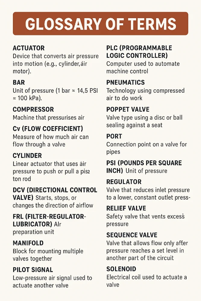
- Actuator: Device that converts air pressure into motion (e.g., cylinder, air motor).
- Bar: Unit of pressure (1 bar ≈ 14.5 PSI ≈ 100 kPa).
- Compressor: Machine that pressurises air.
- Cv (Flow Coefficient): Measure of how much air can flow through a valve.
- Cylinder: Linear actuator that uses air pressure to push or pull a piston rod.
- DCV (Directional Control Valve): Starts, stops, or changes the direction of airflow.
- FRL (Filter-Regulator-Lubricator): Air preparation unit.
- Manifold: Block for mounting multiple valves together.
- Pilot Signal: Low-pressure air signal used to actuate another valve.
- PLC (Programmable Logic Controller): Computer used to automate machine control.
- Pneumatics: Technology using compressed air to do work.
- Poppet Valve: Valve type using a disc or ball sealing against a seat.
- Port: Connection point on a valve for pipes.
- PSI (Pounds per Square Inch): Unit of pressure.
- Regulator: Valve that reduces inlet pressure to a lower, constant outlet pressure.
- Relief Valve: Safety valve that vents excess pressure.
- Sequence Valve: Valve that allows flow only after pressure reaches a set level in another part of the circuit.
- Solenoid: Electrical coil used to actuate a valve.
- Spool Valve: Valve type using a sliding spool to direct flow between ports.
15. Conclusion and Decision-Making Framework
We’ve covered a lot of ground! From basic principles to specific valve types, applications, and maintenance. Pneumatic pressure control valves are essential little workhorses in so many industries.
15.1 Summary of Key Selection Criteria
When choosing a valve, remember the key things to think about:
- Function: What job does it need to do? (Relief, Reduce, Direct…)
- Performance: Flow rate (Cv), pressure range, temperature range, response time?
- Actuation: How will it be controlled? (Manual, Solenoid, Pilot…)
- Environment: Where will it live? (Clean, dirty, hazardous, washdown?)
- Materials: Compatibility with air/gas and environment? (Brass, Steel, Plastic…)
- Connections: Port size and type? Manifold mount?
- Fail-Safe: What happens on power loss?
- Cost: Balancing price and needed performance.
15.2 Future-Proofing Your Pneumatic Systems
Think ahead!
- Consider valves with communication capabilities (like IO-Link) even if you don’t use them immediately – it makes future upgrades easier.
- Focus on energy efficiency – it saves money and is better for the planet. Choose correctly sized components and maintain the system well (especially leaks!).
- Use modular designs (like valve manifolds) that allow easier expansion or changes later.
- Keep good documentation!
15.4 Final Recommendations
Pneumatics offer a powerful, reliable, and often cost-effective way to automate tasks. Understanding the different types of pressure control valves and how to select, install, and maintain them correctly is key to building successful systems.
Please contact Mastermac 2000 to source youe pressure control valves, or other pneumatic componentry you need!
Call 07 3344 4711 or Click Here to contact us online.
About MasterMac2000: Your Trusted Pneumatic & Process Automation Partner.
LEADING THE INDUSTRY: Established in 1989, MasterMac2000 has grown to become one of Australia's largest privately owned pneumatic and process automation companies. We stock top-quality brands like Univer, Mack, Tolomatic, Mac, Piab, American, and Rotoflux in Brisbane.
SERVING QLD & NORTHERN NSW: We proudly service Queensland and Northern New South Wales for all your pneumatic and process equipment needs. Our mission is to provide the best pre and post-sales support while actively expanding our client base.
SOURCING HARD-TO-FIND PARTS: Not only do we stock quality components, but we also excel at sourcing those elusive, hard-to-find parts. With our extensive database and global network of contacts, getting the parts you require is as easy as a call to our highly skilled, professional sales team.
DEDICATED TO YOUR SUCCESS:
- Decades of expertise in pneumatics & process automation
- Carefully curated selection of world-class brands
- Exceptional sourcing capabilities for speciality parts
- Knowledgeable sales staff dedicated to finding solutions
- Unwavering commitment to customer service excellence
About The Author
Stuart Havill
Stuart Havill is the owner and manager of MasterMac2000, Queensland's largest privately owned pneumatic and process valve company.
With his early working career as a maintenance fitter for Boral in 1992, Stuart has spent his life in the field of pneumatics and process equipment. He gained extensive experience in plant design, maintenance, repairs, fabrication, and site management.
In 1996, he transitioned to a pneumatic sales technician role at MasterMac2000, where he excelled in key account management, providing cost-effective solutions, and managing a sales team of 9 employees.
Since 2002, Stuart has been the manager at MasterMac2000, overseeing the company's growth and establishing it as a leader in pneumatic automation and process valve engineering. His expertise spans customer training, CRM setup, industrial compressor sizing and installation, and turn-key project management.
Under Stuart's leadership, MasterMac2000 has been servicing the industry since 1988, with 5 full-time sales representatives covering northern rivers NSW, Queensland, Northern Territory, and PNG. The company prides itself on providing the best-priced solutions to all customers in the marketplace.
View Stuart’s LinkedIn profile to learn more about his expertise in pneumatics and process equipment.