Pneumatic Vacuum Conveyors
Contact Us
Vacuum Pneumatic Conveyors: What Works, What Fails, and Why the Details Matter
A pin-sized leak is all it takes: open a one-millimetre hole midway along a powder transfer line and the rate plummets - sometimes by a third - before anyone hears the hiss. No alarms, just sluggish production and a dusty floor. That lone observation still frames my view of Vacuum Pneumatic Conveyors: they are at once robust and unforgiving.
Get the design right and they run for years with almost no moving parts; miss a minor parameter and performance unravels quietly.
This essay unpacks the why and the how for technicians who live with these systems every day, drawing on field notes, published data, and lessons learned supplying parts through MasterMac 2000, the Queensland firm that has specialised in pneumatic automation since 1989.
1. What a Vacuum Conveyor Is (and Is Not)
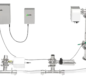
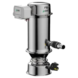
At its simplest, a vacuum conveyor is four elements in series: an air mover, a product feeder, a pipeline, and a separator. Negative pressure - anywhere from –40 kPa for light powders to –90 kPa when a multi-ejector venturi is used - pulls solids into the line.
Because the line is sealed, the material stays contained, and the route can snake around columns, up mezzanines, or through fire-rated walls where belts or screws would choke.
Systems break down further into dilute-phase (high velocity, low solids ratio) and dense-phase (low velocity, higher solids ratio) modes. Technicians often assume vacuum equals dilute. Not true.
Batch dense-phase rigs running –70 kPa can move fragile food granules at 4–6 m s⁻¹ with minimal attrition, provided the feeder meters slowly and the line diameter stays generous. Think weather fronts rather than river rapids: the air makes space; the product follows in cohesive slugs.
2. Why Plants Still Choose Vacuum over Positive Pressure

Containment – The entire line sits under suction, so any pinhole draws air inward, not dust outward. That single feature keeps pharmaceutical rooms in compliance and, frankly, cleaners off night shift.
Layout freedom – Vacuum moves product up to 100 m horizontally and 50 m vertically in a single hop, provided the solids loading stays below roughly 15 kg per kg of air. Long mechanical runs need multiple transfer points and drives.
Low maintenance – Fewer moving parts. Cyclone separators and filter receivers do wear, but gearboxes, chains, and idlers are gone. One plant I service in Logan went from weekly tension checks on a bucket elevator to a quarterly filter change on its new vacuum line. Labour hours dropped 80 %.
Safer product change-outs – Blow a line with air, break two tri-clamps, and hoses come free for clean-in-place. Contrast that with purging a screw conveyor packed with lactose.
3. The Flip-Side: Energy, Air, and Abrasion
Critics are right about the power bill. Vacuum systems draw on either electric blowers or compressed-air ejectors. Energy demand ranges widely - paper-machine audits show from 40 kWh t⁻¹ to well over 120 kWh t⁻¹, depending on fan efficiency and system tuning. Mechanical conveyors rarely exceed 10 kWh t⁻¹. That gap shrinks when the vacuum line replaces multiple mechanical transfer steps, yet it never vanishes.
Then there is abrasion. Hard granites, glass frit, or metal chips eat elbows for breakfast. Technicians try ceramic bends or replaceable sweep fittings, but the truth is: abrasive bulk at high velocity shortens pipe life, whatever the lining. Some operators accept monthly elbow swaps; others revert to drag-chain conveyors and live with their dust issues.
The final drawback is noise. High-speed exhaust at 85 dBA may breach state regulations unless the blower is housed. Queensland’s 8-hour exposure limit hovers at 85 dBA, so an enclosure or a silenced exhauster quickly moves from “nice-to-have” to statutory requirement.
4. Anatomy of a Reliable Install
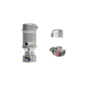
Air mover selection
• Multi-stage centrifugal blowers dominate below –60 kPa.
• Venturi ejectors (no rotating parts) excel in sanitary zones but devour compressed air, roughly 0.6 Nm³ min⁻¹ per tonne conveyed - equipment vendors rarely quote that figure up-front.
• Hybrid packages pair a small positive-displacement exhauster with an ejector that kicks in only for surge loads.
Feed device
The most overlooked point. If a rotary valve leaks air, it quenches the vacuum and starves the line. In one Ipswich cereal plant, swapping a loose-tolerance iron valve for a machined stainless model lifted throughput 22 % at the same fan speed - proof that small clearances matter.
Velocity window
Textbook tables say keep dilute-phase velocity above saltation (~17 m s⁻¹ for flour). On site, I aim for 18–20 m s⁻¹ at pickup, then accept a 10 % drop at the receiver. Too low and plugs form; too high and filters blind early.
The balance shifts with humidity and fines content, so static tables only get you to commissioning. After that, watch the differential pressure gauges.
Elbow count
Every 90° bend adds the equivalent of 5–7 m of straight pipe to pressure loss. Three extra bends in a retrofit can kill a design margin. Map the route, question every corner, and budget for long-radius glass elbows in high-wear spots.
Filtration and cleaning
Cyclone-plus-baghouse combos capture 99.9 % of fines under 5 µm when sized correctly. Automated reverse-pulse cleaning at 0.6 MPa keeps ΔP stable, but pay attention to diaphragm valve life.
Technicians at MasterMac 2000 stock spare diaphragms because delivery times can stretch to six weeks when overseas freight bottlenecks.
5. Common Pneumatic Conveyor Failure Modes and How to Anticipate Them
| Symptom | Likely Cause | First Check | Long-Term Fix |
| Plugged line | Air velocity below saltation | Is the blower VSD set-point down? | Increase air or reduce feed rate; consider larger bore |
| Frequent filter blinding | Humid air condensing | Receiver exhaust temperature | Inline air heater or desiccant dryer |
| Product attrition | Excessive velocity | Orifice plate reading | Dense-phase mode or baffled drop leg |
| Energy spikes | Leaking suction hose | Vacuum gauge drift | Replace hose, add leak-down test in PM routine |
Blockages top the list. Industry case studies flag insufficient airflow and overfeeding as prime culprits. My own logs show 70 % of calls hinge on the feeder, not the fan.
6. A Brief Case Study - Fine Sugar, Tight Space, Low Noise
Last year a confectionery plant outside Brisbane needed to lift icing sugar from floor sacks to a mixer 8 m up, across 30 m of horizontal pipe, and do it inside a noise-sensitive neighbourhood. Our team at MasterMac 2000 supplied a 7.5 kW side-channel blower, a hygienic feed adapter, and a 60 mm stainless line. Initial trials stalled: the sugar caked at pickup. We bumped velocity to 21 m s⁻¹ and added a vibratory agitator on the feed hopper.
Throughput settled at 1 t h⁻¹, utilisation 95 % - not record-setting, but under the 80 dBA target thanks to a composite blower enclosure. Power intensity pencilled out at ~55 kWh t⁻¹, mid-pack for dilute-phase. Three months in, filters remain below 1 kPa ΔP; a reality check that practical tweaks outrun theoretical spreadsheets.
7. Counterarguments in Good Faith
“Mechanical conveying is cheaper.”
Capital often is, especially for short horizontal runs under 20 m. But add dust extraction, fire separation, and weekly greasing, and price parity narrows quickly.
“Vacuum cannot handle abrasive product.”
True, to a point. Alumina or sand at high velocity will erode bends. Dense-phase or sacrificial ceramic elbows extend service life, though a drag chain may still win in the long game.
“Energy costs negate the benefits.”
Not entirely. Plants that replace three belt transfers and a bucket elevator with one vacuum line saw net power drop after factoring all drives and dust collectors off the ledger. Context rules.
8. Uncertainties and Open Questions
While blower curves predict static pressure nicely, the human factor - maintenance culture, operator tweaks - keeps outcomes messy. One shift may throttle back airflow to “save energy,” unaware they are edging toward saltation. Data loggers show the trend, but only if someone checks them. In that sense, the line is only as smart as the technicians watching it.
Emerging tech muddies the view further. Low-voltage turbo blowers promise 10 % efficiency gains, but field data remain scarce. Likewise, AI-driven control loops claim to balance feed rate and pressure in real time; yet every pilot I have seen still hands control back to manual during CIP cycles.
9. Conclusion - Back to the Pin-Hole
That earlier pin-hole taught me two lessons. First, vacuum conveyors are unforgiving of leaks - integrity beats horsepower. Second, the best-laid design still needs vigilant eyes on gauges and filters. This essay has walked through fundamentals, pitfalls, and real-world compromises, yet it barely touches regulatory dust limits or the true lifecycle-cost calculus.
My analysis leans on published data and a slice of field work, but material diversity, operator behaviour, and economic swings mean no table of numbers stays definitive for long.
So a closing question for every plant team: How will you know - tomorrow, not yesterday - that your line is running inside its sweet spot? Answer that and your vacuum conveyor will likely behave, leak or no leak. Ignore it, and the next sluggish transfer may already be forming quietly in the pipe.
Call 07 3344 4711 or Click Here to contact us.